I have been working on a pair of Pass Labs Aleph Five single-ended class-A monoblock amplifiers for about two and a half years. In truth, it is about 3 weeks of work, it’s just been spread out over a very long period!
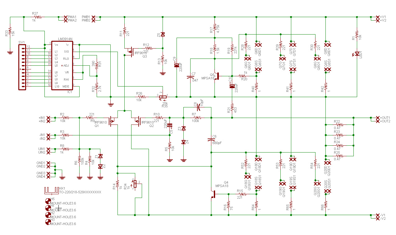
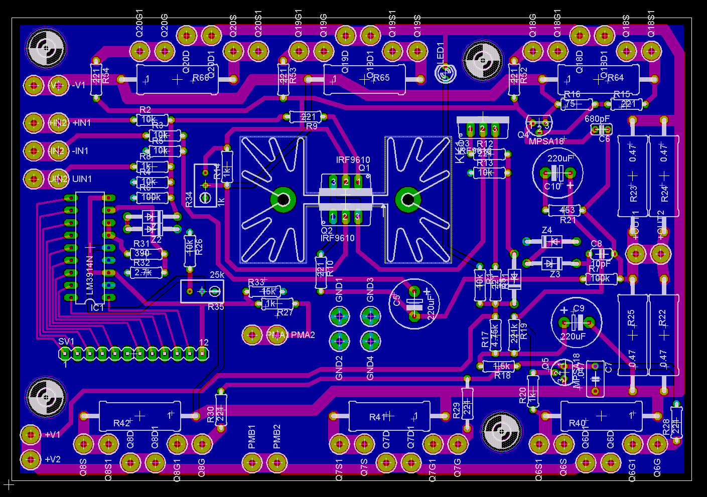
The schematic is based on that published in the Pass Labs service manual, with several modifications. Here is the schematic:
A few notes are in order:
- All the input and output connectors are doubled. This is because I used 1/4″ spade lugs that require two mounting holes. Placing double connectors on the schematic makes it easier to place double holes on the board.
- +IN and -IN are for balanced connections. UIN is unbalanced.
- R34 and R35 are 10-turn precision potentiometers. R34 adjusts DC offset at the speaker terminals and R35 adjusts the level on the LED VU meter.
- Connections PMA and PMB are for a switch that disables the VU meter.
- The current source MOSFETS (Q6-8) and the output MOSFETS (Q18-20) are not on the schematic because they are remoted to large heat sinks and replaced on the schematic by the spade lugs to which they connect. Each connection is labeled for gate, source or drain. All of these transistors are IRFP-244’s and should be matched to within 0.01V.
- Q1 and Q2 should be matched to each other as well.
- R22-25, R40-41, and R64-66 are 3W. All others are 1/4W.
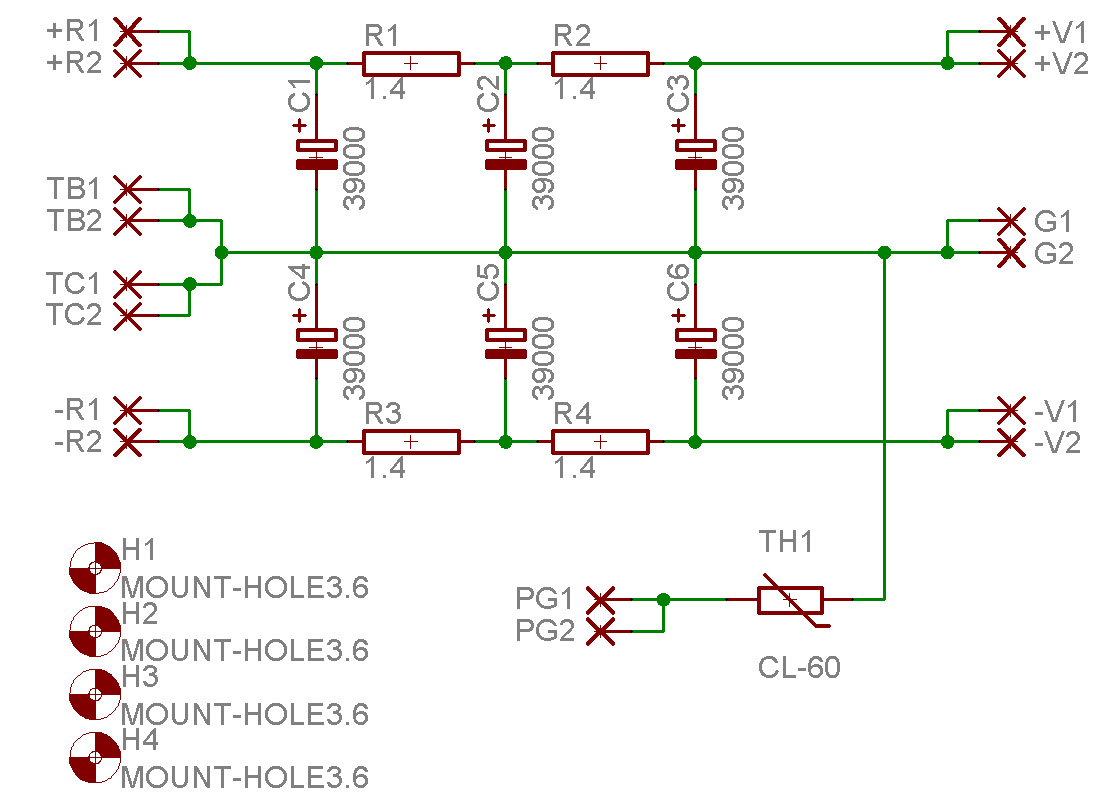
Here is the power supply schematic:
Notes:
- Filter section is a CRCRC design. The resistors, R1-4, are 50W and are mounted so as to use the rear of the power supply chassis as a heat sink.
- TH1 is a thermistor between the circuit ground and chassis ground to limit ground loop noise.
- TB and TC are the transformer center taps used to establish the ground level.
- +R and -R are the outputs of a 35V 4A bridge rectifier.
- Filter capacitors are Panasonic TUP type, 39,000uf 50V.
- The transformer is a 30V 500VA toroidal, Avel Lindberg model number Y236802
- The switch, rectifier, fuse, current inrush limiters, etc. are all outside the schematic. The switch is a Soft Switch V2 from diyAudio regular Rob Cheng.
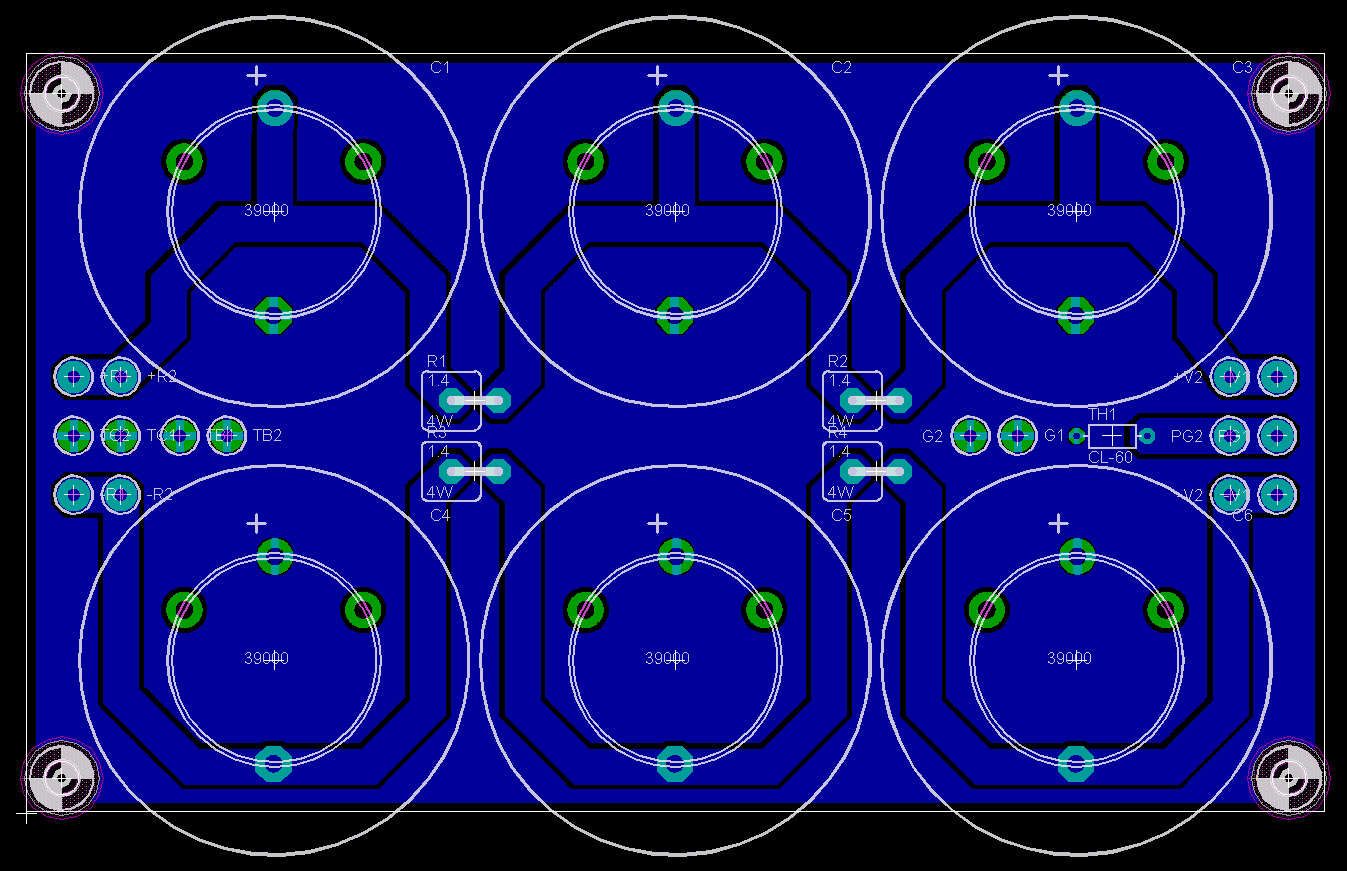
If you have Eagle CAD, you can download the schematics and board layouts below. Otherwise, JPEGs of the board layouts follow.
Here is the power supply – there are two of these, one for each channel.
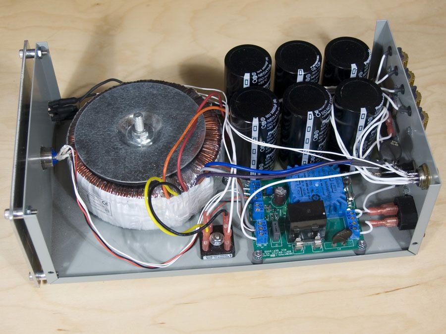
Aleph Five Power Supply
Here is the rear portion of the power supply – soft switch on the right, filter caps on the left.
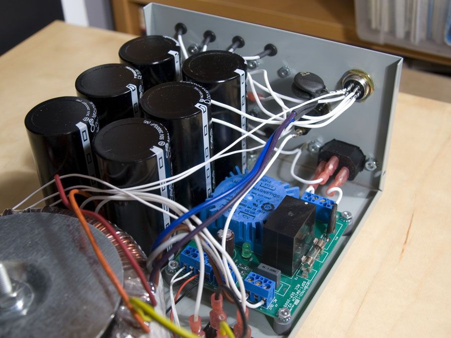
Power Supply Detail
This is the back of the power supply chassis. You can see R1-4. There is a 120°C thermal switch mounted on the inside of the rear panel. The 5-pin connector at the upper left carries power, ground and thermal switch sensing to the main amplifier chassis.
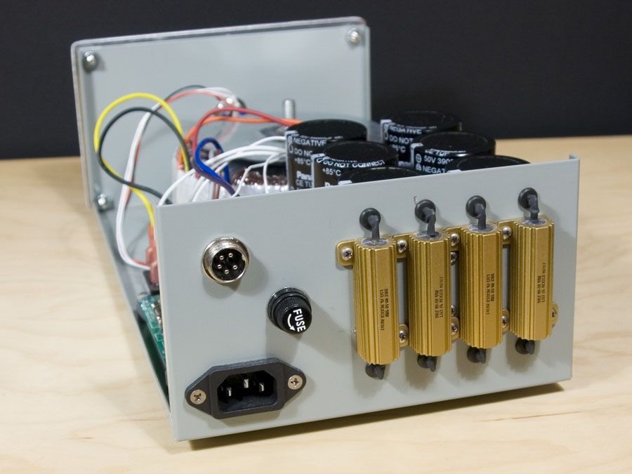
Rear of Power Supply
The center of the front panel is dominated by the power switch. The three LEDs monitor the Fuse, the Power Supply Thermal Switch and the Amp Thermal Switches. There are three of the latter, one mounted on each of the main heat sinks in the main amp chassis.
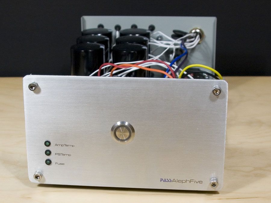
Front Panel of Power Supply
Love those LEDs!
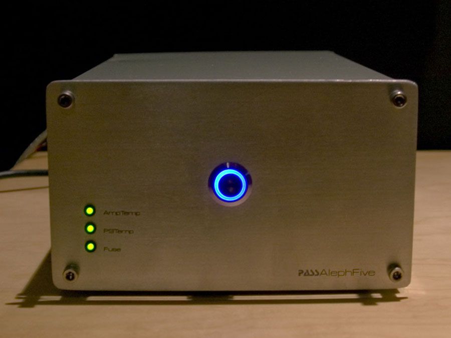
Power and Status Lights
The main chassis aren’t done yet. Or rather, they aren’t started yet. Here is the testing prototype, which does work and sounds really good.
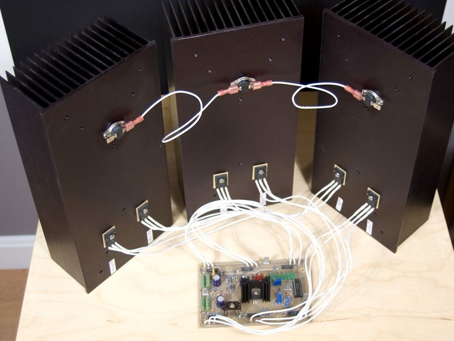
Amp Prototype
And here are the final revision circuit cards, ready to be stuffed.
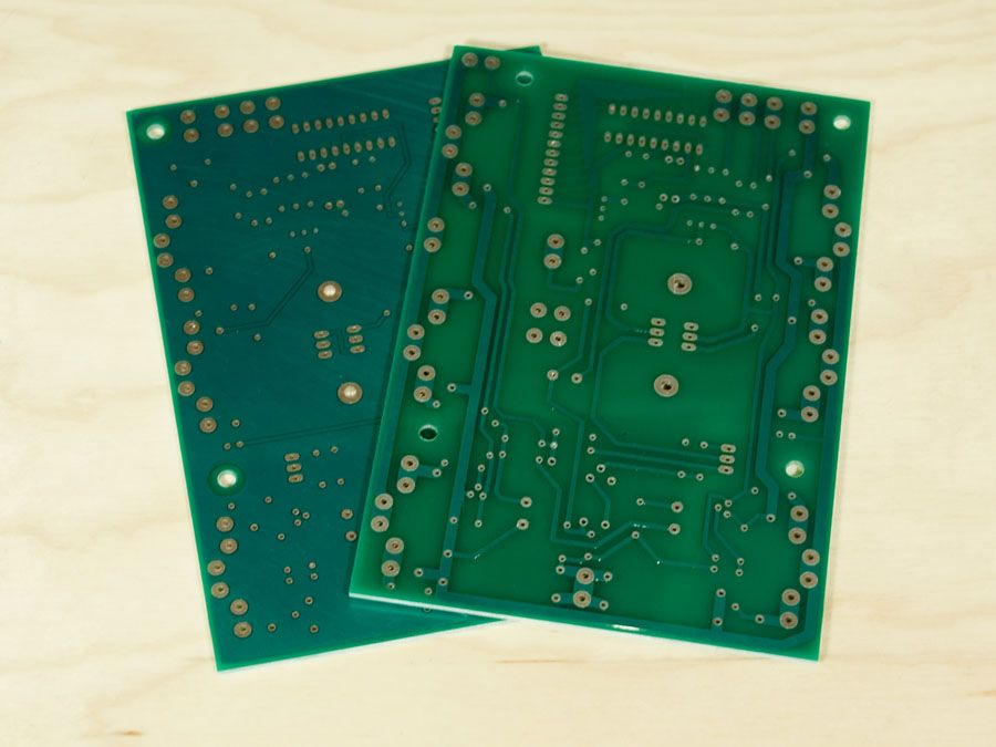
Final Revision Amp Cards
My hope is that posting it here means I will finally get it finished this decade. Stay tuned…
Hi There — Found your blog through DIYAUDIO re: the Aleph 5 — Did you ever finish your build? Did you make extra PCBs that you’re willing to part with? Thanks for all the good insight…cheers!
I think your gate stoppers should be on the fets, not the PCB. Could be trouble otherwise….
could you make me an aleph 5?
Seeing as how I still haven’t finished mine, I’m gonna go with “no”. 🙂