Oct 162009
 

I’ve had several requests for the wiring diagrams for my Line Source Speakers, so here it is!

Basically, all systems like this are wired in series-parallel. Individual drivers are wired in series, then the series banks are wired in parallel with each other. How many drivers to put in series and how many banks in parallel is dictated by the nominal impedances of the drivers, and what you want the total impedance to be. Remember, impedance adds in series, and is the reciprocal of the sum of the reciprocals in parallel (see formula on the image below).

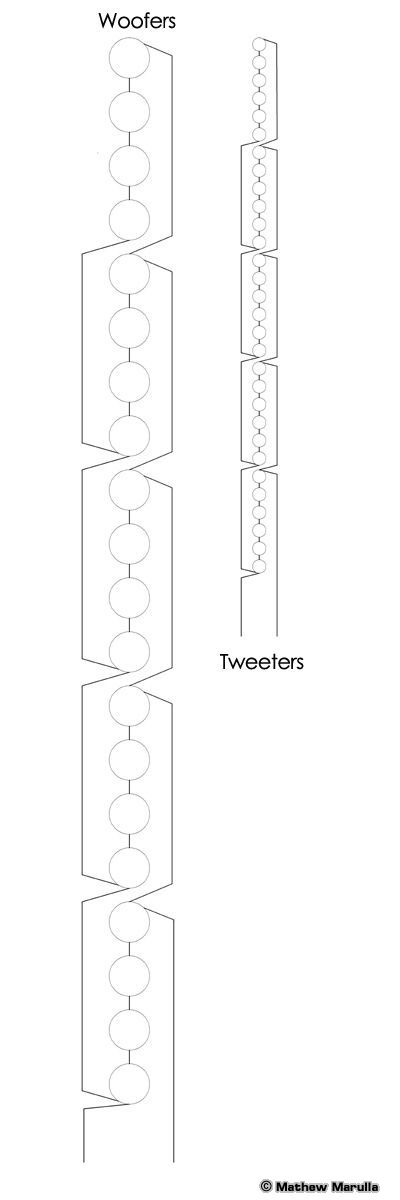
In the case of these speakers, I really lucked out… The woofers were nominally 6Ω each and I planned to have twenty of them. The tweeters were 4Ω each and I wanted thirty of them. So it all worked out as shown here.

Line Source Wiring

So with four woofers per series bank and six tweeters per bank, all banks add up to 24Ω. Five of each bank means that twenty woofers is 4.8Ω and thirty tweeters is exactly the same!

When doing the actual wiring it helps to make a diagram with the drivers swung into their actual configuration as shown below. Keeps you from getting confused as you connect the wires.

Line Source Wiring

Jul 232009
 

I have been working on a pair of Pass Labs Aleph Five single-ended class-A monoblock amplifiers for about two and a half years. In truth, it is about 3 weeks of work, it’s just been spread out over a very long period!

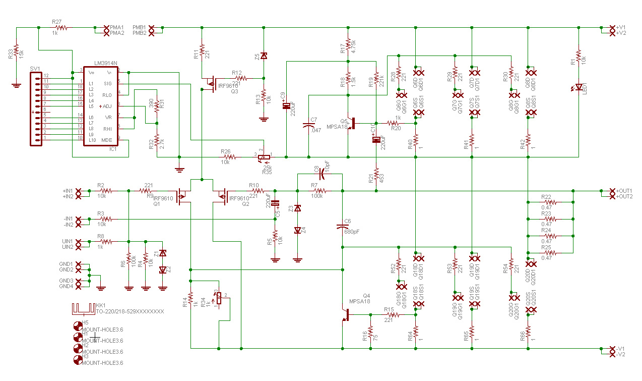
The schematic is based on that published in the Pass Labs service manual, with several modifications. Here is the schematic:

Aleph Five Schematic (click for full size)

A few notes are in order:

  1. All the input and output connectors are doubled. This is because I used 1/4″ spade lugs that require two mounting holes. Placing double connectors on the schematic makes it easier to place double holes on the board.
  2. +IN and -IN are for balanced connections. UIN is unbalanced.
  3. R34 and R35 are 10-turn precision potentiometers. R34 adjusts DC offset at the speaker terminals and R35 adjusts the level on the LED VU meter.
  4. Connections PMA and PMB are for a switch that disables the VU meter.
  5. The current source MOSFETS (Q6-8) and the output MOSFETS (Q18-20) are not on the schematic because they are remoted to large heat sinks and replaced on the schematic by the spade lugs to which they connect. Each connection is labeled for gate, source or drain. All of these transistors are IRFP-244’s and should be matched to within 0.01V.
  6. Q1 and Q2 should be matched to each other as well.
  7. R22-25, R40-41, and R64-66 are 3W. All others are 1/4W.

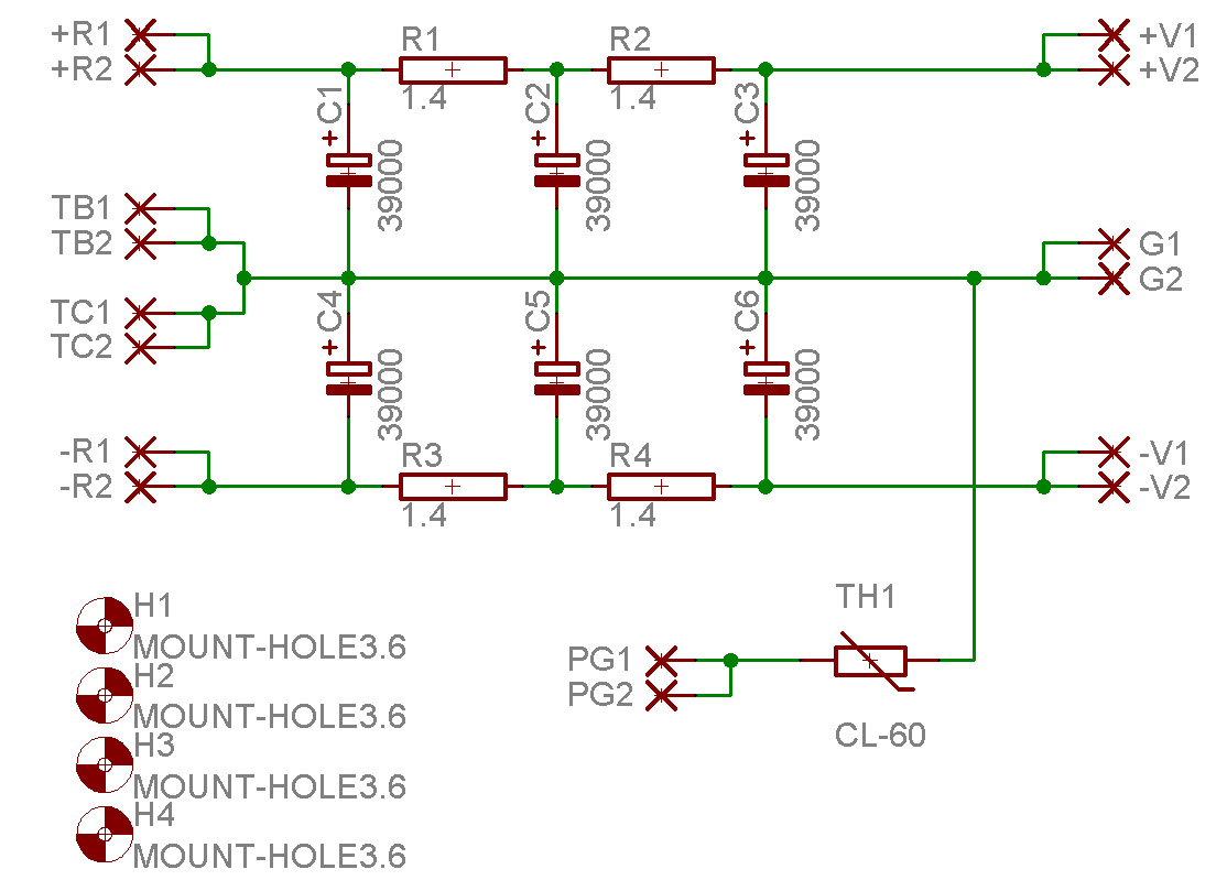
Here is the power supply schematic:

Aleph Five PS Schematic (click for full size)

Notes:

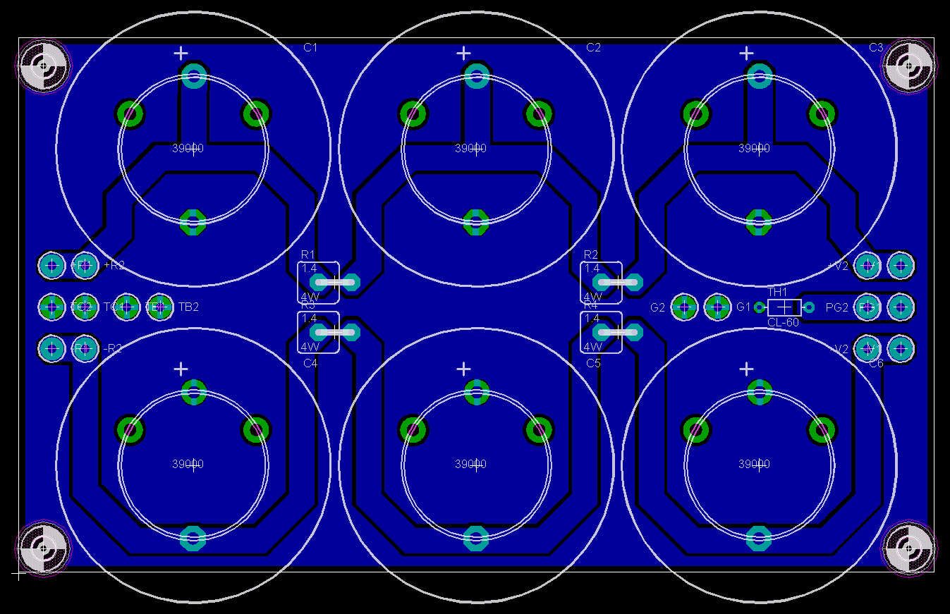
  1. Filter section is a CRCRC design. The resistors, R1-4, are 50W and are mounted so as to use the rear of the power supply chassis as a heat sink.
  2. TH1 is a thermistor between the circuit ground and chassis ground to limit ground loop noise.
  3. TB and TC are the transformer center taps used to establish the ground level.
  4. +R and -R are the outputs of a 35V 4A bridge rectifier.
  5. Filter capacitors are Panasonic TUP type, 39,000uf 50V.
  6. The transformer is a 30V 500VA toroidal, Avel Lindberg model number Y236802
  7. The switch, rectifier, fuse, current inrush limiters, etc. are all outside the schematic. The switch is a Soft Switch V2 from diyAudio regular Rob Cheng.

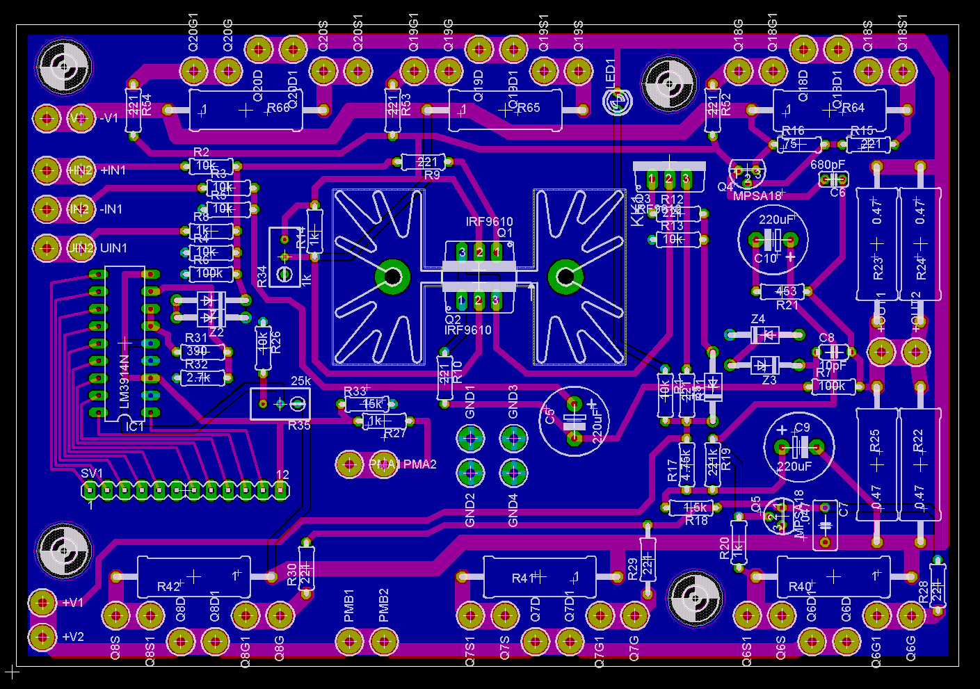
If you have Eagle CAD, you can download the schematics and board layouts below. Otherwise, JPEGs of the board layouts follow.

Aleph Five Board Layout (click for full size)

Power Supply Board Layout (click for full size)

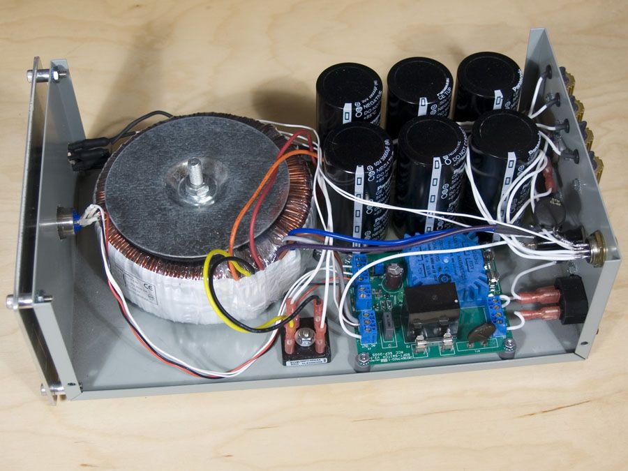
Here is the power supply – there are two of these, one for each channel.

Aleph Five Power Supply

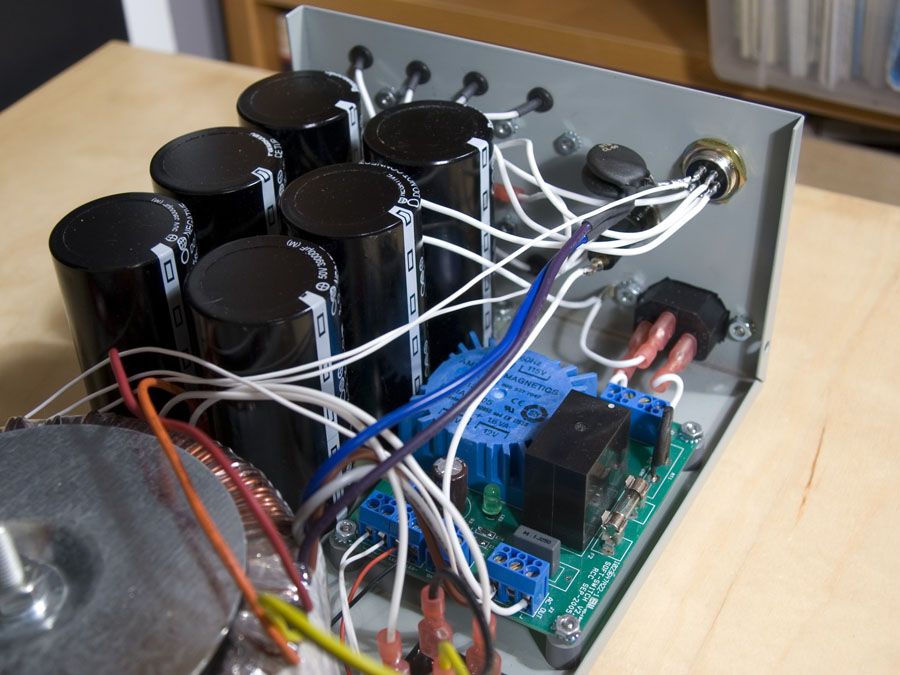
Here is the rear portion of the power supply – soft switch on the right, filter caps on the left.

Power Supply Detail

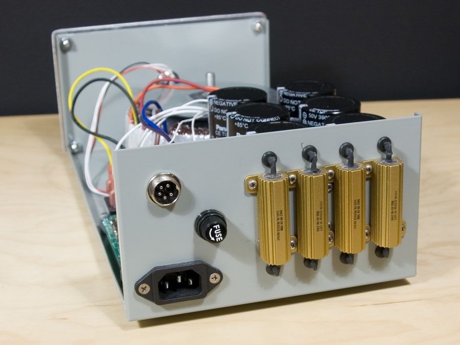
This is the back of the power supply chassis. You can see R1-4. There is a 120°C thermal switch mounted on the inside of the rear panel. The 5-pin connector at the upper left carries power, ground and thermal switch sensing to the main amplifier chassis.

Rear of Power Supply

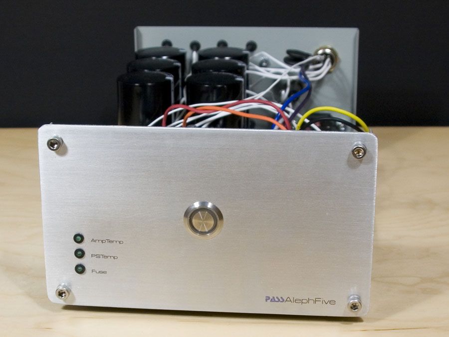
The center of the front panel is dominated by the power switch. The three LEDs monitor the Fuse, the Power Supply Thermal Switch and the Amp Thermal Switches. There are three of the latter, one mounted on each of the main heat sinks in the main amp chassis.

Front Panel of Power Supply

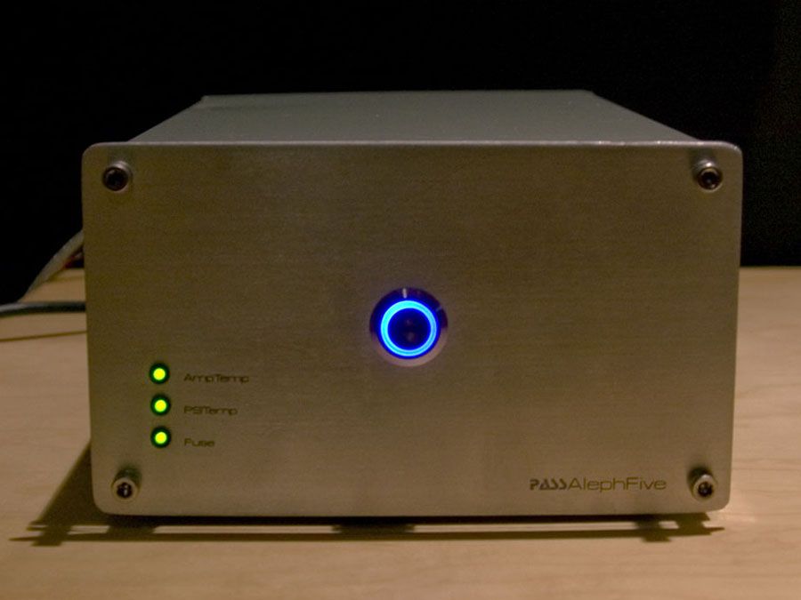
Love those LEDs!

Power and Status Lights

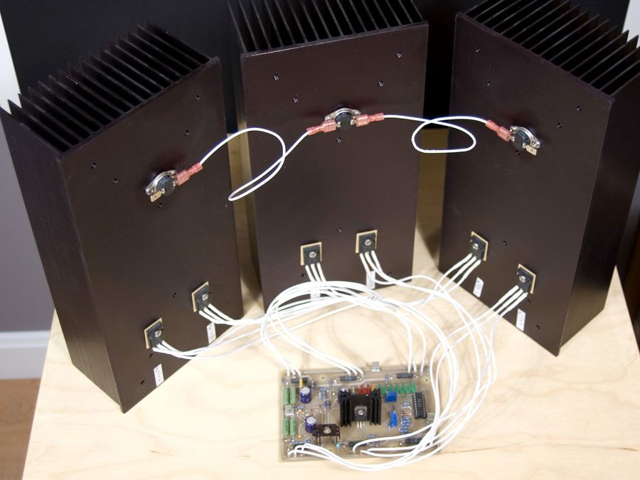
The main chassis aren’t done yet. Or rather, they aren’t started yet. Here is the testing prototype, which does work and sounds really good.

Amp Prototype

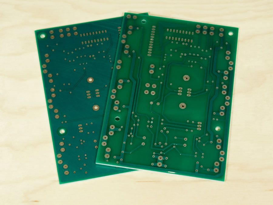
And here are the final revision circuit cards, ready to be stuffed.

Final Revision Amp Cards

My hope is that posting it here means I will finally get it finished this decade. Stay tuned…

Jul 312007
 

I’ve wanted to build a line source array for quite a while. The barrier has always been cost – a single driver might be $15 – $30, but build a speaker with 40 or 50 of those drivers and the price gets a little insane.

Well, the tweeters were a no-brainer. Parts Express has had 3/8″ mylar dome tweeters made by Onkyo for quite a while at $0.25 each. The performance is pretty good, but they were designed for a specific automotive application so the construction makes them impossible to flush mount. But, at only $15 for sixty of them, I’d find a way to make them work.
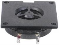
Specs

Power Handling: 20 watts RMS/40 watts max
VCdia: 3/8″
Znom: 4 ohms
Re: 3.50 ohms
Frequency range: 6,000-20,000 Hz
Fs: 4,200 Hz
SPL: 87 dB 2.83V/1m

It wasn’t until very recently that I found a bargain on woofers to make these speakers a reality. Made by Hi-Vi Research, these 3″ shielded mid/woofers have a square frame which makes them easier to mount in an array.
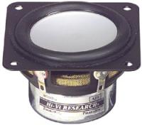
Specs

Power Handling: 15 watts rms / 30 watts peak
Znom: 6 ohm
VCdia: 3/4″
Re: 5.2 ohms
Frequency range: 85-9000 Hz
SPL: 82db 1w/1m
Vas: 0.05 cu ft
Qms: 4.68
Qes: 0.43
Qts: 0.39
Fs: 85 hz
Xmax: 2.85mm

So here is the plan: 80 inches tall with 30 tweeters and 20 woofers in each speaker for a total of 100 drivers, each channel a mirror image of the other. The tweeters would have to be back-mounted, so a 3/4″ round-over makes for a nice pseudo-horn effect. The backs are to be open and the speakers equalized to flat response in the actual listening environment.
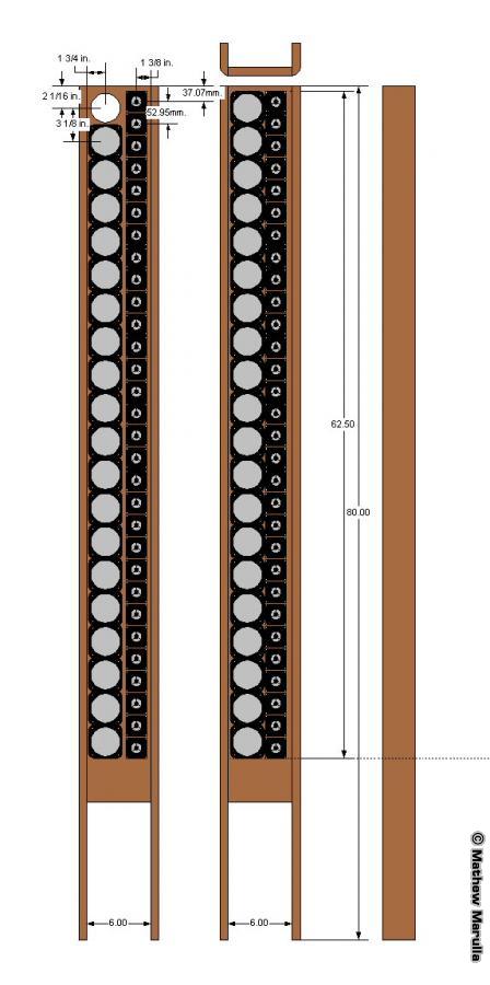
Line Source Plan

The early construction was nothing but lots and lots and lots of drilling. Sorry, no pics of that joy. First, mounting the tweeters.
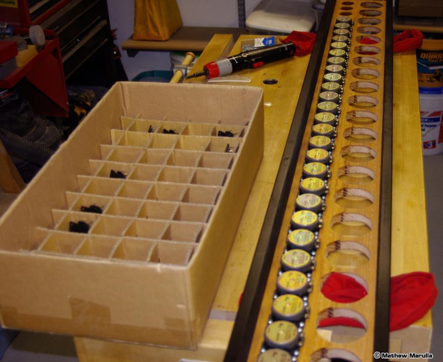
Mounting the Tweeters

Then, getting the woofers unpacked and ready for install.
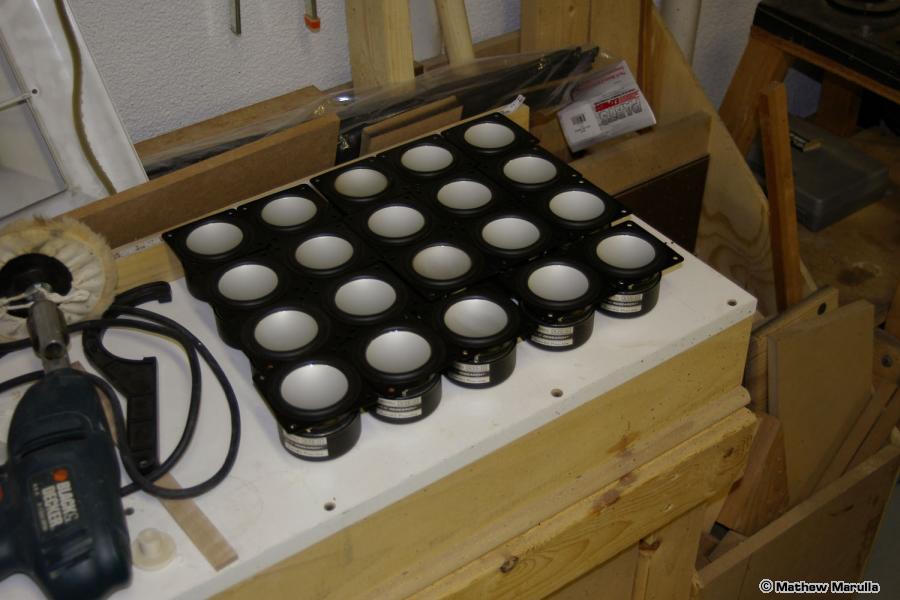
Woofers Ready for Mounting

The holes for the woofers were pretty tight, not leaving a lot of wiggle room to get all the spacing exact. By darkening the space between the woofers with a magic marker, a little misalignment goes unnoticed. You can see a nice detail of the rounded-over tweeter holes here too.
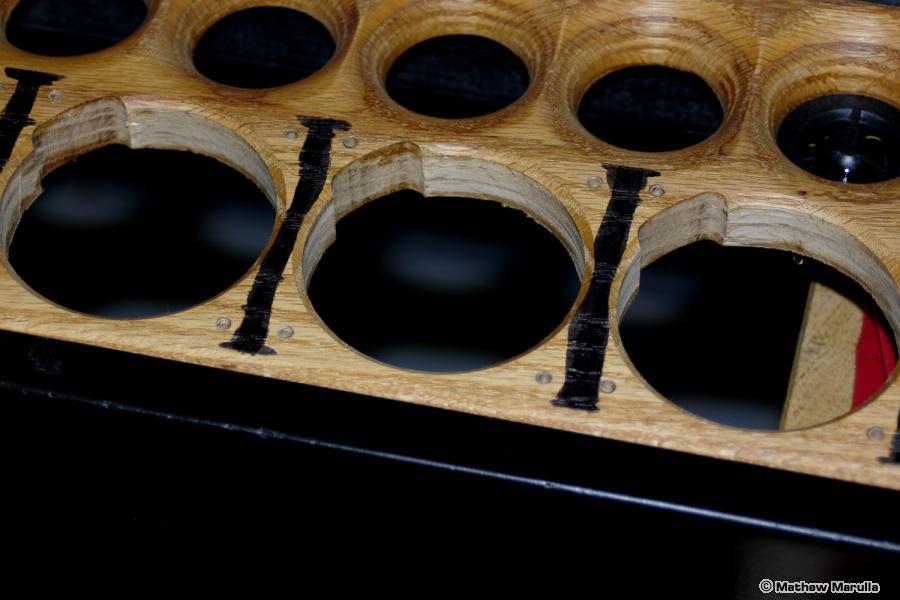
Darkening the Intra-Woofer Spaces
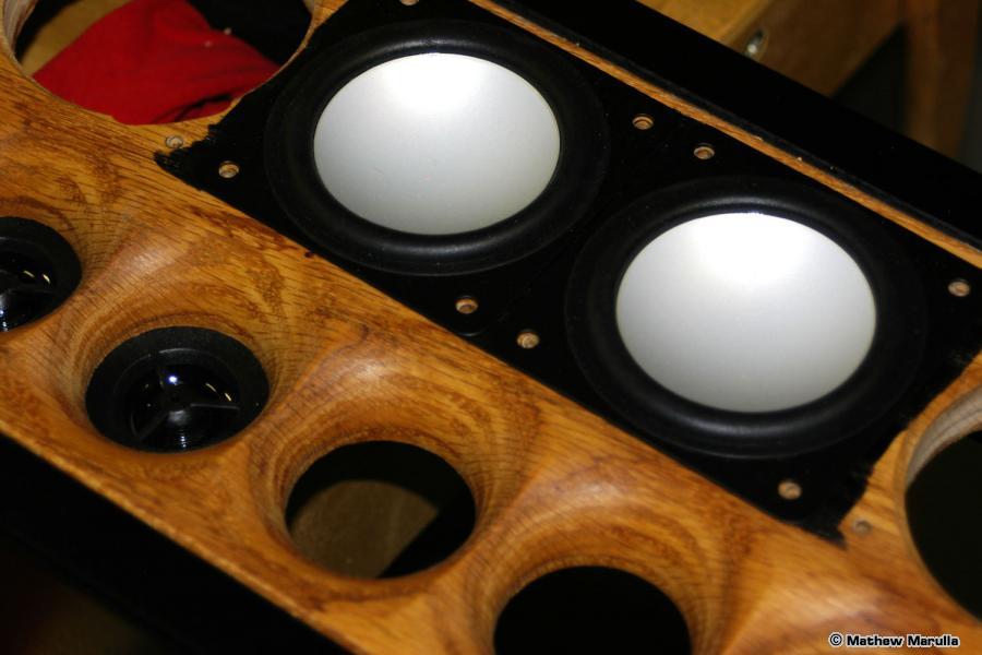
A Handy Cheat!

Mounting the woofers. The terminals do not fully clear the woofer holes, so I had to do “wire-as-you-go” while installing the woofers.
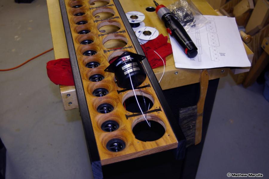
Mounting the Woofers

Everything finally mounted and wired. That’s only 100 driver holes, 400 mounting holes, and 200 soldered connections!
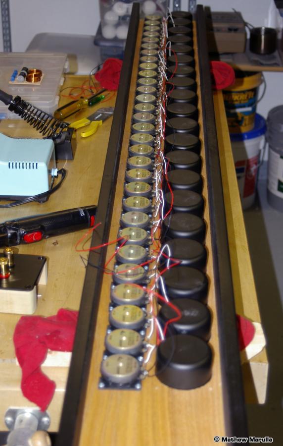
Everything Mounted and Wired

Here’s a shot of the crossover network (24db at 7500Hz), and the terminal panel.
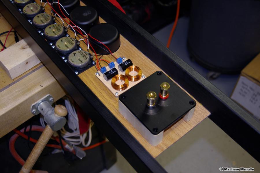
Crossover and Terminals

The base took some special consideration. After everything was mounted, I was surprised at the weight. I guess 50 drivers add up! Also, since they were over six feet tall, I needed to make sure that tipping would be a non-issue. So I used a pair of machine screws and dowel nuts per leg, and an oversize base.
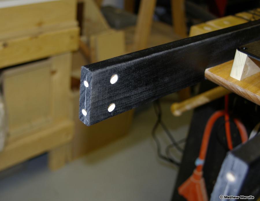
Holes for Dowel Nuts
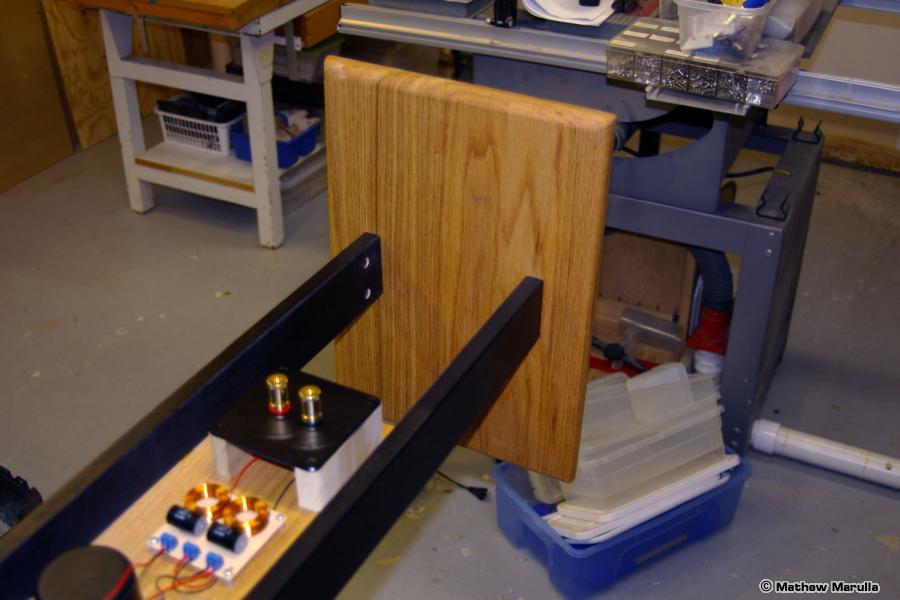
Base Attached

And that’s all, folks!

The sound was a little nasal at first, but I expected some equalization would be required. First a bass boost because the woofers, at 3″, were never designed to go very low. However, 20 of them together have almost as much area as a 15″ woofer. Handling the power of such a boost is easy since the input power is split 20 ways. Second, there was a little bump around the crossover point to tame. And finally, the tweeters were not exactly flat from the factory.

I used a pair of mono 1/3 octave equalizers from Audio Control, a TrueRTA spectrum analyzer and a Behringer calibrated microphone a to get things pretty flat, but after a few hours use it wandered from that goal by quite a bit. I let the drivers break in for about 200 hours and then re-equalized.

After getting dialed in, the sound is pretty amazing. Here are the finished speakers in my listening room.
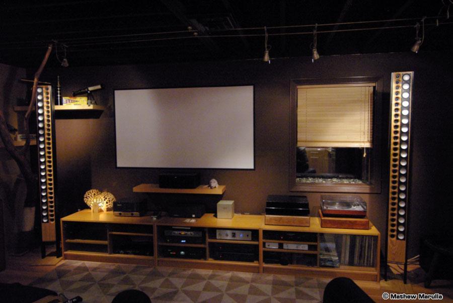
Line Source Speakers in Place